Posts

DIY Motion-Activated Relay Control using Arduino
Image
  Introduction Have you ever wanted to create a simple motion-activated project using Arduino? In this tutorial, we'll guide you through building a motion-activated relay control system using a Passive Infrared (PIR) sensor and an Arduino board. This project is perfect for beginners and provides a hands-on introduction to working with sensors and actuators. Components Needed Arduino board (e.g., Arduino Uno) Passive Infrared (PIR) sensor Relay module Jumper wires Breadboard Wiring the Components First, let's set up the hardware. Connect the PIR sensor and relay module to the Arduino as follows: PIR sensor: Connect the sensor's VCC pin to 5V on the Arduino. Connect the GND pin to GND on the Arduino. Connect the OUT pin to digital pin 5 on the Arduino. Relay module: Connect the VCC pin to 5V on the Arduino. Connect the GND pin to GND on the Arduino. Connect the IN or signal pin to digital pin 6 on the Arduino. Ensure that your connections are secure and double-check the speci...

Interfacing Ultrasonic Sensor, Relay Module, and 16x2 I2C LCD with Arduino

Image
  Introduction In this tutorial, we'll explore how to interface an ultrasonic sensor, a relay module, and a 16x2 I2C LCD with an Arduino board. This project allows you to measure distance using the ultrasonic sensor, control a relay based on the distance, and power on the STM32 module when the distance is above 5cm. The distance and relay status are displayed on a 16x2 I2C LCD. Components Needed Arduino board Ultrasonic sensor Relay module 16x2 I2C LCD STM32 module Jumper wires Wiring Connections Follow these wiring instructions to connect the components: Ultrasonic Sensor: VCC → +5V on Arduino GND → GND on Arduino Trig → Digital Pin 2 on Arduino Echo → Digital Pin 3 on Arduino Relay Module: VCC → +5V on Arduino GND → GND on Arduino Control → Digital Pin 4 on Arduino STM32 Module: Power → Relay Common Pin (NO) on Relay Module GND → GND on Arduino 16x2 I2C LCD: VCC → +5V on Arduino GND → GND on Arduino SDA → SDA on Arduino SCL → SCL on Arduino Arduino Code #include <Wire.h> #i...

"Building a Clap Switch with Arduino: A Fun and Interactive Electronics Project"

Image
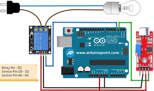
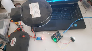
  Introduction Welcome to our Arduino project series! In this tutorial, we'll guide you through the process of creating a Clap Switch using an Arduino, a sound sensor, and a relay module. This interactive project allows you to control electronic devices with the simple gesture of clapping your hands. Components Needed Before we dive into the project, let's gather the necessary components: Arduino (e.g., Arduino Uno) Sound sensor module Relay module LED or any other electronic device for control Jumper wires Breadboard Circuit Connections Let's start by connecting the components to build the circuit: Sound Sensor to Arduino: VCC of the sound sensor to 5V on the Arduino. GND of the sound sensor to GND on the Arduino. OUT of the sound sensor to a digital pin (e.g., D2) on the Arduino. Relay Module to Arduino: VCC of the relay module to 5V on the Arduino. GND of the relay module to GND on the Arduino. IN of the relay module to a digital pin (e.g., D7) on the Arduino. Connect th...

Popular posts from this blog

DIY Door Lock Security System with Arduino and Keypad: A Step-by-Step Guide

Interfacing Ultrasonic Sensor, Relay Module, and 16x2 I2C LCD with Arduino

DIY Motion-Activated Relay Control using Arduino