Introduction
Welcome to our Arduino project series! In this tutorial, we'll guide you through the process of creating a Clap Switch using an Arduino, a sound sensor, and a relay module. This interactive project allows you to control electronic devices with the simple gesture of clapping your hands.
Components Needed
Before we dive into the project, let's gather the necessary components:
- Arduino (e.g., Arduino Uno)
- Sound sensor module
- Relay module
- LED or any other electronic device for control
- Jumper wires
- Breadboard
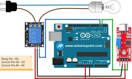
Circuit Connections
Let's start by connecting the components to build the circuit:
Sound Sensor to Arduino:
- VCC of the sound sensor to 5V on the Arduino.
- GND of the sound sensor to GND on the Arduino.
- OUT of the sound sensor to a digital pin (e.g., D2) on the Arduino.
Relay Module to Arduino:
- VCC of the relay module to 5V on the Arduino.
- GND of the relay module to GND on the Arduino.
- IN of the relay module to a digital pin (e.g., D7) on the Arduino.
Connect the Electronic Device to the Relay Module:
- Connect one end of the device to the NO (Normally Open) pin on the relay module.
- Connect the other end of the device to the COM (Common) pin on the relay module.
Arduino Code
Now, let's upload the Arduino code to make it all work:
const int soundSensorPin = 2;
const int relayPin = 7;
void setup() {
pinMode(soundSensorPin, INPUT);
pinMode(relayPin, OUTPUT);
}
void loop() {
int soundValue = digitalRead(soundSensorPin);
if (soundValue == HIGH) {
// Clap detected, toggle the relay state
digitalWrite(relayPin, !digitalRead(relayPin));
delay(1000); // Add a delay to prevent multiple toggles from a single clap
}
}
Explanation
- The sound sensor detects claps by monitoring sound levels.
- The Arduino responds to a clap by toggling the relay, acting as a switch.
- The relay, in turn, controls the connected electronic device (e.g., LED or lamp).
Tips and Notes
- Adjust the sound sensor sensitivity using its potentiometer.
- Consider using an external power supply for the relay module if needed.
- This is a basic example; feel free to modify and expand based on your preferences.
Conclusion
Congratulations! You've successfully built a Clap Switch using Arduino. This project not only provides a hands-on experience with electronics but also opens the door to more exciting Arduino projects. Stay tuned for more tutorials in our Arduino project series!
If any project requirement Contact me on +918973147676 Thank you.

Comments
Post a Comment