Introduction
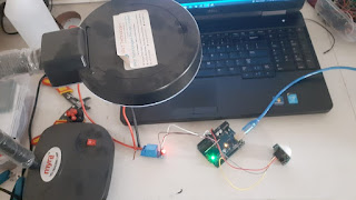
In this tutorial, we'll explore how to interface an ultrasonic sensor, a relay module, and a 16x2 I2C LCD with an Arduino board. This project allows you to measure distance using the ultrasonic sensor, control a relay based on the distance, and power on the STM32 module when the distance is above 5cm. The distance and relay status are displayed on a 16x2 I2C LCD.
Components Needed
- Arduino board
- Ultrasonic sensor
- Relay module
- 16x2 I2C LCD
- STM32 module
- Jumper wires
Wiring Connections
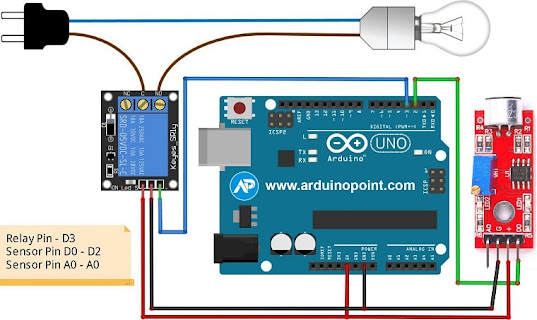
Follow these wiring instructions to connect the components:
Ultrasonic Sensor:
- VCC → +5V on Arduino
- GND → GND on Arduino
- Trig → Digital Pin 2 on Arduino
- Echo → Digital Pin 3 on Arduino
Relay Module:
- VCC → +5V on Arduino
- GND → GND on Arduino
- Control → Digital Pin 4 on Arduino
STM32 Module:
- Power → Relay Common Pin (NO) on Relay Module
- GND → GND on Arduino
16x2 I2C LCD:
- VCC → +5V on Arduino
- GND → GND on Arduino
- SDA → SDA on Arduino
- SCL → SCL on Arduino
Arduino Code
#include <Wire.h>
#include <LiquidCrystal_I2C.h>
// Define the ultrasonic sensor pins
const int trigPin = 2;
const int echoPin = 3;
// Define the relay control pin
const int relayPin = 4; // Change this to the actual pin you've connected the relay control to
// Define the LCD settings
LiquidCrystal_I2C lcd(0x27, 16, 2); // I2C address 0x27, 16 columns and 2 rows
// Variables for duration and distance
long duration;
int distance;
void setup() {
// Initialize Serial communication
Serial.begin(9600);
// Initialize LCD
lcd.init();
lcd.backlight();
lcd.print("Distance:");
// Set ultrasonic sensor pins as OUTPUT and INPUT
pinMode(trigPin, OUTPUT);
pinMode(echoPin, INPUT);
// Set relay pin as OUTPUT
pinMode(relayPin, OUTPUT);
}
void loop() {
// Trigger the ultrasonic sensor
digitalWrite(trigPin, LOW);
delayMicroseconds(2);
digitalWrite(trigPin, HIGH);
delayMicroseconds(10);
digitalWrite(trigPin, LOW);
// Measure the duration of the echo signal
duration = pulseIn(echoPin, HIGH);
// Calculate the distance in centimeters
distance = duration * 0.034 / 2;
// Clear the LCD
lcd.clear();
// Display distance on the LCD
lcd.setCursor(0, 0);
lcd.print("Distance: ");
lcd.print(distance);
lcd.print(" cm");
// Control the relay based on distance
if (distance > 5) {
// Turn on the relay
digitalWrite(relayPin, LOW);
lcd.setCursor(0, 1);
lcd.print("Status: STM32 ON");
} else {
// Turn off the relay
digitalWrite(relayPin, HIGH);
lcd.setCursor(0, 1);
lcd.print("Status: STM32 OFF");
}
// Add a delay between measurements
delay(1000);
}
Explanation
In the Arduino code, the relay Pin is utilized to control the relay module. When the ultrasonic sensor detects a distance greater than 5cm, the relay is activated (digital Write(relayPin, LOW)), completing the circuit and providing power to the STM32 module. Conversely, when the distance is 5cm or less, the relay is deactivated (digital Write(relayPin, HIGH)), cutting off power to the STM32 module. This mechanism allows you to remotely power on or off the STM32 module based on the proximity detected by the ultrasonic sensor.
Conclusion
This project not only demonstrates the integration of an ultrasonic sensor, a relay module, and a 16x2 I2C LCD but also showcases how these components can be used to automate the power control of external devices, such as the STM32 module. As always, feel free to experiment and modify the code to suit your specific requirements.
If any project requirement Contact me on +918973147676 Thank you.
.jpeg)


Comments
Post a Comment